Project Overview
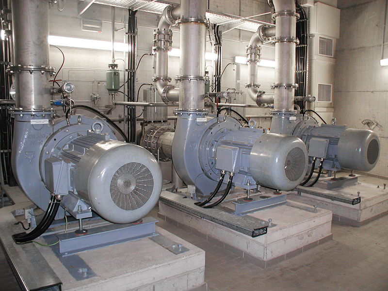
Background InformationAs part of a self-directed engineering project, I undertook the complete design of a Low Temperature Hot Water (LTHW) circulation pump for a commercial HVAC application. The project was framed to replicate a real-world scenario faced by mechanical design engineers working in consultancy or OEM environments, where system requirements are translated into a fully engineered, manufacturable product rather than selected from a catalogue.
The focus was on designing a centrifugal pump from first principles, considering not only hydraulic performance but also mechanical integrity, reliability, and suitability for continuous HVAC operation. The outcome was a pump design defined in sufficient detail to proceed directly into CAD modelling and fabrication.
Project Aim:The primary aim of the project was to develop a repeatable, first-principles-based pump design methodology that could be applied to HVAC and clean-water applications. Rather than relying on manufacturer performance curves, the goal was to design the pump internally, defining all major hydraulic and mechanical components based on system-level inputs.
A secondary aim was to simulate the type of end-to-end ownership expected of a mechanical design engineer, from interpreting client requirements through to producing a fabrication-ready concept suitable for validation and manufacture.
Objectives:1. Translate HVAC system requirements (flow rate, pressure, operating conditions) into a defined pump duty point.
2. Apply turbomachinery theory to design the impeller, including diameter, blade geometry, and flow passages.
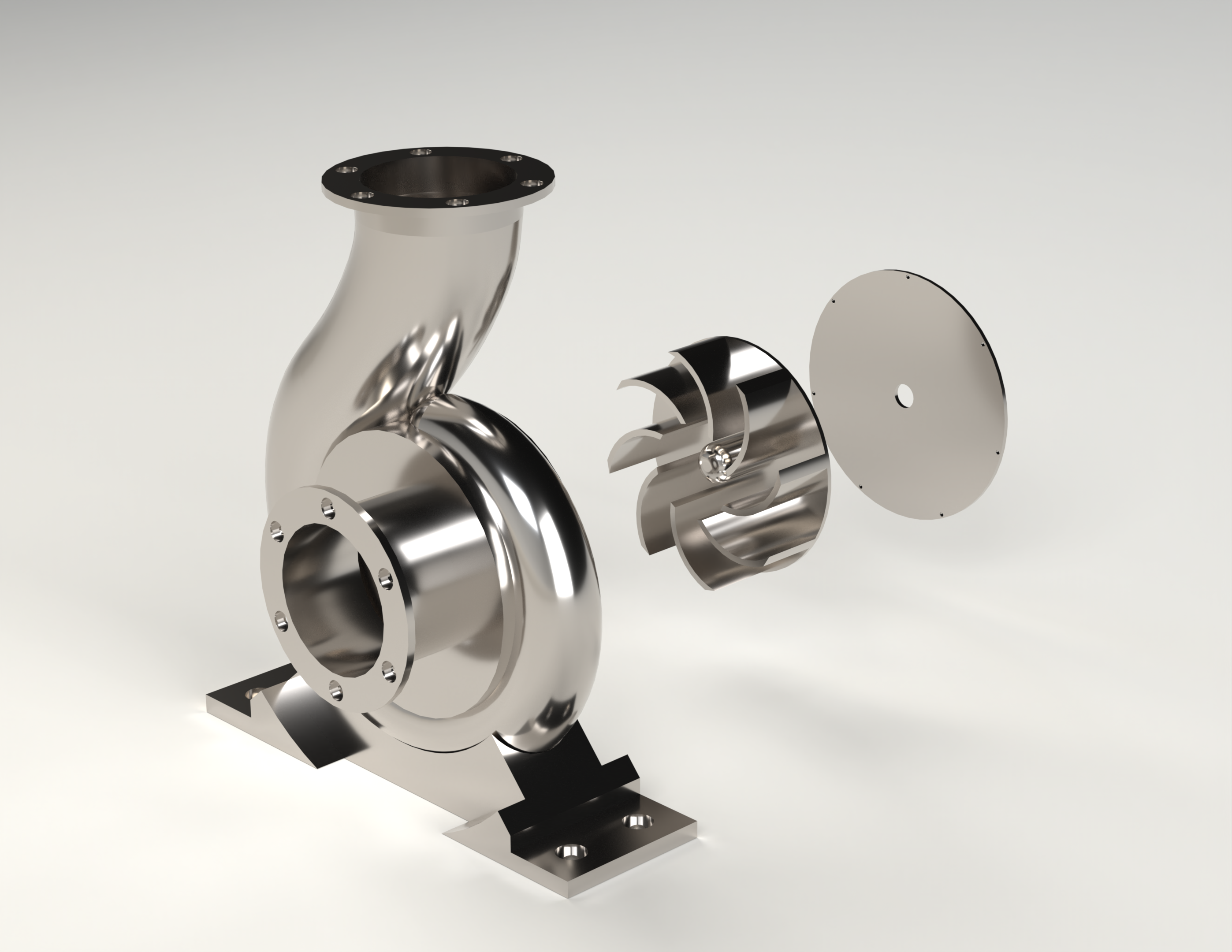
3. Design the pump casing and volute to enable efficient pressure recovery.
4. Size and specify the shaft, bearings, and mechanical seal for continuous-duty operation.
5. Ensure the final design is mechanically robust, manufacturable, and suitable for CAD development.
6. Produce a design process that can be replicated for future pump or fluid machinery projects.
Tasks Conducted:
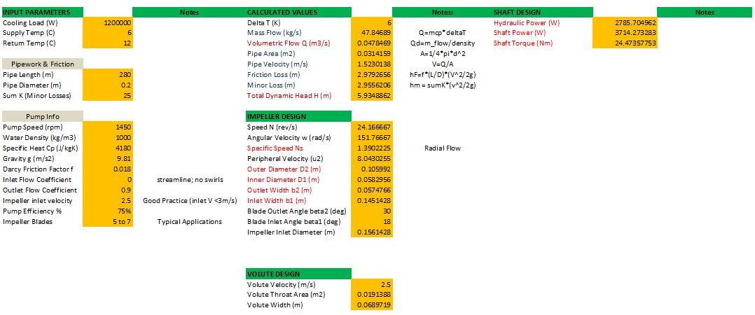
1. Interpreted system-level LTHW requirements to establish pump flow rate and differential head.
2. Converted pressure requirements into hydraulic head and defined the pump duty point.
3. Selected an appropriate pump type and rotational speed based on efficiency, noise, and reliability considerations.
4. Designed the impeller from first principles, including inlet eye sizing, outlet diameter, blade count, and blade angles.
5. Applied continuity and energy equations to define impeller flow passage widths and velocities.
6. Developed the volute casing concept to convert velocity head into pressure head efficiently.
7. Calculated hydraulic power, shaft power, and torque to size the pump shaft.
8. Selected bearings based on load, speed, and target service life.
9. Defined a suitable mechanical seal arrangement based on pressure, temperature, and operating regime.
10. Considered material selection and manufacturability for all major pump components.
11. Structured the final output to be directly transferable into CAD for detailed modelling and validation.
Engineering Challenges
One of the main challenges was balancing theoretical pump design equations with practical engineering judgement. While turbomachinery theory provides the foundation for energy transfer and flow behaviour, real-world considerations such as cavitation risk, noise, manufacturability, and component availability strongly influence final design decisions.
Another challenge was ensuring that the design process remained generalised and repeatable, rather than becoming overly tailored to a single operating point. This required careful explanation and justification of assumptions, design coefficients, and empirical limits typically used in industry.
Additionally, designing supporting components such as bearings and mechanical seals required consideration of long-term reliability, shaft deflection, thermal limits, and compatibility with HVAC operating conditions.
Project Photos
.png)
.png)